Last change: 08/01/2002
To sum it up, this is ONLY about problems with the fundamental functions of the board.
This is a collection of forum postings to this subject.
It is based on my experiences with two Dragon Plus boards from two different traders and my solution. I do not claim that all boards sold are affected, nor do I promise that the method described in here will cure your problems. I can just tell you what my experiences are.
My system configuration is:
The problems only happened after some time, and more often when the computer was on for some time. About the first few minutes it was ok, then the trouble began. Lockups occured more often with a closed case.
My system always locked up randomly when the case was closed and especially during SiSoft Sandra memory burn-in test. In Sandra, it even failed with an open case, although less often.
Failure when
testing with
DocMemory
on DOS-Bootdisk, which gave memory errors at random locations.
Important: There were no bit-errors during the pattern check (like FFFF is FFEF
when reading) which hint to faulty memory but whole byte errors (FFFF written,
but AAAA read), which means that whole read/write operations must have failed.
After the computer had been on for some time, the problems worsened - even
DocMemory crashed with errors, and DOS itself too.
I pointed fans towards different regions of the board and saw that stability improved at some locations. I applied heat sinks where I found hot chips and where I thought the problem could be.
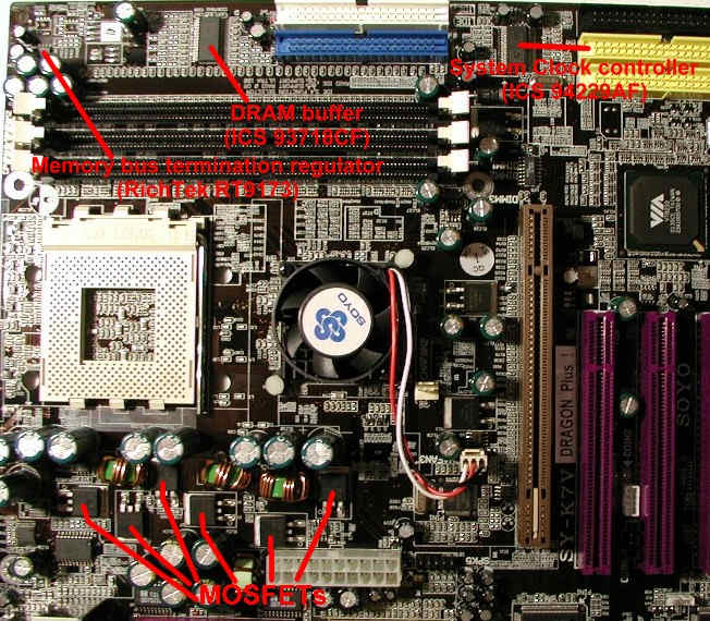
The third thing I tried was a tiny IC surrounded by capacitors. It was -like all the others- too hot to touch. It is the memory bus termination voltage regulator Richtek RT9173.
I put a huge heat sink on it - the lockups nearly ceased as long as the case was open. Sandra showed a mean no-lockup time of about 15 cycles in 5 test runs. Before, the mean time was about 2 cycles.
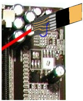
Heat sink (blue, left) on the memory
termination regulator. Locate the five capacitors - they are the same as on the
picture above. The picture's orientation is the same as well.
This IC is the only one that has an overheat shutdown feature, which is triggered at 150°C (datasheet here). You might say it could never become that hot, but it is pretty small, heats up fast, and the capacitors around it may stop the airflow. It is also too small to dissipate much heat.
See the picture above to locate the components.
I suspect that it is a design failure by Soyo - either they have choosen the wrong chip (there is an RT9173A chip available which can handle double current) or they have used only one in order to save a few bucks. If you examine the board more closely, you will see that there are unused soldering points for two more of these ICs nearby - labeled as U32 and U35. In older versions (Soyo SY-K7V Dragon, not Plus!), two of these chips were soldered in, as well as on very recent Dragon Plus! boards. Had Soyo noticed the mistake ?
The sink I applied is 30x15 mm in size (cut-down CPU heat sink ;-) ) and still gets hot, about 50°C. So I think that an IC case with a size of 5x3 mm could never dissipate enough energy !
Layout of the memory bus termination
Schematics
of a sample DDR mainboard
On the dragon, the components are as follows:
So what is it's purpose of this regulator ? It should provide a constant voltage of 1.25 V which is needed to terminate the bus.
Why this ? I'll keep it short and simple:
The memory works at
a voltage of 2.5 V, but its "zero" voltage is set at 1.25 V. The data is
transferred by signals which are 1.25 V above and below the "zero" voltage. So
if you take 1.25 V as "zero", the signals will be between 0 V and 2.5 V. So you
need to terminate to that 1.25 voltage as well, not plain to the ground. And you
need an IC which will produce this 1.25 V. This is the Richtek RT9173. It is
specified to handle a current up to 1.5 A, and will transfer the input voltage
from the power supply (5 V) to the 1.25 V that are needed.
What if if gets to hot and fails ? Well, the termination will most probably not work anymore, leaving your memory corrupted, with the results shown above.
It may or not be a design failure to use just one of these regulators with an overall current of 1.5 A. There are many other chips around, and they all offer currents of at least 2-3 A. And most of them have special heat-sinking capabilities: A heat bridge to the PCB layer (soldering on the back) and a larger package, which can dissipate more heat.
I wanted to fix this problem for now and forever, so I exchanged the chip.
There is a pin-compatible version of this chip available from the manufacturer RichTek. The 1.5 A version is called RT9173, the 3 A version is called RT9173A.
(Specifications for both chips can be found here)
I got a free sample of the RT9173A chips from RichTek in Taiwan:
Eric Tzu, Sales Division, Field
Application Dept., Manager
RichTek Technology Corp.
Tel: 886-2-89191466 ext. 300
Fax: 886-2-89191465
Mobil: 0921-923494
E-mail: eric_tzu@richtek-ic.com.tw
Web: www.richtek-ic.com.tw
He has been very kind and sent me the samples by express mail (btw. as I am CEO of a small company I could ask him as a business customer, not end user - maybe they won't send samples to an end user or charge you for this).
The RT9173A has a different and larger package, so it won't fit to the old soldering points. I had to make a small second PCB where I could mount it.
The old 1.5 A chip (below) and the new 3 A one
(above). The scale is not the same, the upper one is much larger than depicted.
This soldering is not for the faint at heart, but it can be done. Best way is to first cut-off the old chips pins rather than soldering it out, so the board will not get that hot. After that, I made a small board on which I soldered the new chip, because it has a different pin layout and package size. I soldered the edge of this board directly to four pins on the mainboard, but you can also use thin wires. The four pins in the other row on the board all connect to the middle pin of the new chip, so use a small cable. If you use a board with copper surface, solder the back of the chip to the tiny board as well, so the heat is dissipated by the copper. It will still get pretty warm, but not hot enough to fail.
The board is mounted on a 45° angle,
so the copper layer touches the mainboard at the soldering points.
See this picture:
You can do this with a usual soldering iron if you are careful, just use a thin head. The new chip is not SMD but normal sized. The specifications of both regulation chips can be found here.
After my first board worked again, I gave the the second, unpatched one away to my father. He tried the board with his own components, and had the same lockups as me before. On my advice he did the same resoldering on his board (without all that other extensive testing before), and his board ran fine as well from then on. However, the new copper PCB on both boards and the new chip still get very warm when you touch them - about 50-60°C at load. So you can imagine how much that tiny IC had to stand...
All questions regarding this FAQ should be directed to the thread "Dragon + Instability" at the ViaArena forum, where we've been discussing this topic for a long time.
I'd like to thank everyone on the forum who helped me with this FAQ by sharing his experiences.
André Lang (a.k.a. "Sierra")